PCBA production is rarely about one machine or one process.
A complete electronics manufacturing line may involve solder paste printing, component placement, reflow soldering, inspection, through-hole assembly, cleaning, testing, and final handling.
The challenge is that a small problem at one stage can easily become a much larger problem later.
From my experience working with SMT and THT equipment, here are several common problems that electronics manufacturers face — and the equipment or process improvements that can help solve them.
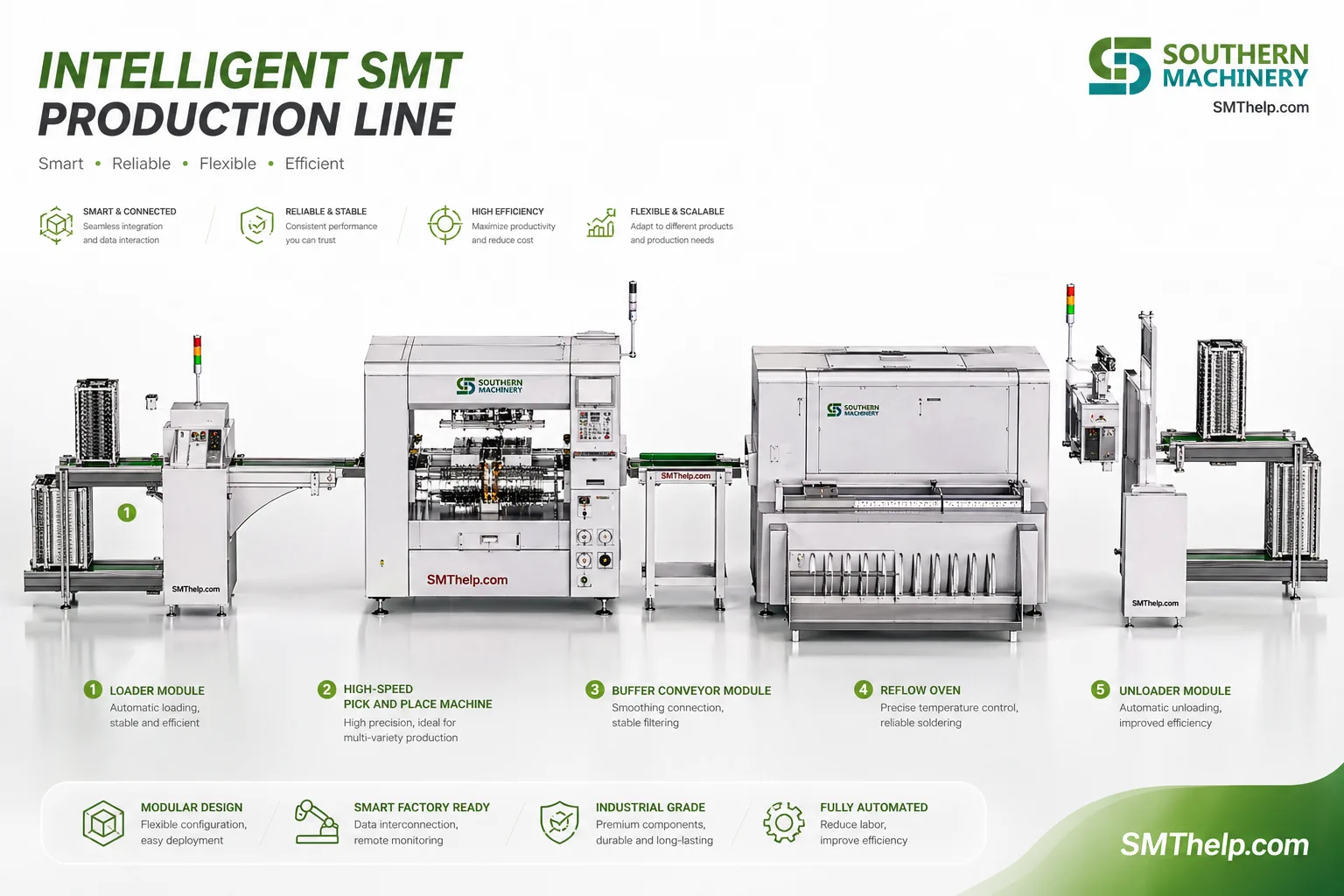
1. Solder Paste Printing Problems
Many PCBA defects actually begin before a single component is placed.
Common problems include:
- Too much or too little solder paste
- Poor stencil alignment
- Blocked stencil apertures
- Uneven solder paste height
- Solder paste drying or changing viscosity
These issues may later cause insufficient solder joints, bridging, tombstoning, or open circuits.
This is why many SMT lines use SPI — Solder Paste Inspection immediately after printing.
SPI systems can measure solder paste height, area, volume, and position before the PCB enters the pick-and-place machine.
Finding a printing problem early is much cheaper than finding it after reflow.
2. Component Placement Errors
Modern pick-and-place machines can place thousands of components per hour, but speed alone does not guarantee quality.
Production problems can still happen because of:
- Incorrect feeder setup
- Nozzle wear
- Component pickup failure
- Wrong component orientation
- Feeder vibration instability
- Poor component recognition
For standard SMD components, these problems are normally managed through machine vision, feeder maintenance, and nozzle inspection.
However, unusual components such as connectors, LEDs, transformers, switches, or odd-shaped parts may require customized feeders or gripper nozzles.
This is especially common when manufacturers move from manual assembly toward higher automation.
Sometimes the problem is not the placement machine itself.
The real limitation is how the component is presented to the machine.
3. Reflow Soldering Problems
Reflow soldering is one of the most critical processes in SMT production.
Typical defects include:
- Cold solder joints
- Solder bridging
- Tombstoning
- Component shifting
- Insufficient wetting
- Excessive oxidation
- PCB deformation
The temperature profile is extremely important.
The PCB needs to pass through preheating, soaking, reflow, and cooling stages under controlled conditions.
For this reason, manufacturers often focus on:
- Heating-zone stability
- Conveyor stability
- Temperature uniformity
- Nitrogen atmosphere
- PCB support systems
- Thermal profiling
Thin or large PCBs can also bend during heating.
For some applications, center support systems or adjustable PCB support pins can help reduce deformation during reflow.
For power electronics and semiconductor applications, the requirement may be even higher.
Vacuum reflow technology can be used to reduce voids inside solder joints, especially for applications such as power modules, DBC or AMB substrates, and high-reliability electronics.
4. Inspection Finds the Problem Too Late
One of the most expensive situations in electronics manufacturing is discovering a defect after several downstream processes have already been completed.
This is why inspection is increasingly integrated directly into the production line.
Common inspection equipment includes:
Automatic Optical Inspection
Automatic Optical Inspection can detect defects such as:
- Missing components
- Wrong components
- Polarity errors
- Solder defects
- Component offset
Both 2D and 3D AOI systems are widely used depending on the application.
X-Ray Inspection
X-Ray inspection becomes important when the solder joint cannot be seen directly.
Typical applications include:
- BGA
- QFN
- Power modules
- Hidden solder joints
- Voids
AOI and X-Ray do not replace process control.
Their real value is helping manufacturers understand where the process is becoming unstable.
5. THT Assembly Still Depends Too Much on Manual Labor
Many people associate modern electronics production with SMT, but through-hole components are still widely used.
Examples include:
- Large capacitors
- Connectors
- Transformers
- Relays
- Radial components
- Axial components
- Mechanical components
These parts are common in automotive electronics, industrial control, power electronics, appliances, LED products, and many other applications.
The challenge is that THT assembly can require a large amount of manual labor.
For higher-volume production, manufacturers may consider:
- Radial insertion machines
- Axial insertion machines
- Odd-form insertion machines
- Bowl feeders
- Vibratory feeders
- Customized component feeding systems
Automation does not always mean automating every component.
In many factories, the most practical strategy is to automate the repetitive components first and keep low-volume or complex components for manual assembly.
This hybrid approach can often provide a better return on investment.
6. Soldering After THT Insertion Creates New Challenges
After through-hole insertion, the next challenge is soldering.
Traditional wave soldering is still widely used for high-volume production.
However, modern PCB designs are becoming more complex.
Some boards contain both SMT and THT components, while certain areas cannot be exposed to a full wave soldering process.
In these situations, selective soldering can be a useful solution.
Selective soldering applies flux and solder only to specific areas of the PCB.
It is especially suitable for:
- Mixed SMT/THT assemblies
- High-value PCBs
- Low-to-medium production volumes
- Components with difficult soldering locations
- Applications requiring tighter process control
The correct choice between wave soldering and selective soldering depends heavily on the PCB design, production volume, component layout, and quality requirements.
7. PCB Cleaning Is Often Overlooked
Cleaning is sometimes treated as a secondary process.
But contamination can create long-term reliability problems.
PCBA contamination may include:
- Flux residue
- Dust
- Ionic contamination
- Oil
- Fingerprints
- Small particles
For high-reliability electronics, medical electronics, automotive electronics, industrial control, and conformal coating applications, cleanliness can become especially important.
Different applications may require different cleaning methods, including:
- Inline PCB cleaning
- Batch cleaning
- Water-based cleaning
- Solvent cleaning
- Brush or air cleaning
- Plasma cleaning
There is no single cleaning machine suitable for every PCBA.
The first question should always be:
What contamination are you trying to remove?
Only after answering that question does it make sense to select the cleaning process.
Final Takeaway
When a factory experiences production defects, replacing one machine is not always the answer.
A reflow defect may actually begin with solder paste printing.
A placement problem may come from the feeder rather than the placement machine.
A soldering defect may actually come from PCB design or component lead condition.
A cleaning problem may be caused by the wrong flux chemistry.
This is why PCBA production should be viewed as a complete process rather than a collection of individual machines.
The best equipment solution usually starts with understanding:
- PCB size and structure
- Component types
- Production volume
- Current process
- Existing equipment
- Main defects
- Automation target
- Quality requirements
Once these factors are clear, equipment selection becomes much easier.
For EMS and electronics manufacturers, the goal is not simply to add more machines.
The goal is to make the production process more stable, repeatable, and efficient.