An automatic soldering machine is often judged by its motion system, temperature controller or solder-wire feeder. But the small part that finally meets the joint deserves just as much attention: the soldering iron tip.
In robot soldering, PCBA soldering and manual rework alike, the tip transfers heat from the heater to the work. It contacts the solder, pad, lead or terminal directly, so its shape, dimensions, working surface and condition all influence the final solder joint. A well-matched tip helps the process reach the joint efficiently and repeatedly; an unsuitable one can make an otherwise capable machine difficult to tune.
This guide explains the role of soldering tips in automated applications, common PC, D, DV1 and DV2 styles, and the information that helps when a standard tip is not the right fit.
What Is a Soldering Iron Tip?
A soldering iron tip is the removable working end of a soldering tool. In an automatic soldering machine or soldering robot, it sits at the end of the heated soldering unit and is positioned by the machine over a programmed solder joint.
The tip has two jobs at once. It must carry heat quickly from the heating system, and it must present that heat to a very specific area without disturbing nearby parts. That is why it is more than a simple metal point. Its geometry, contact area, internal material and plated working surface are selected to balance heat transfer, durability and wetting.
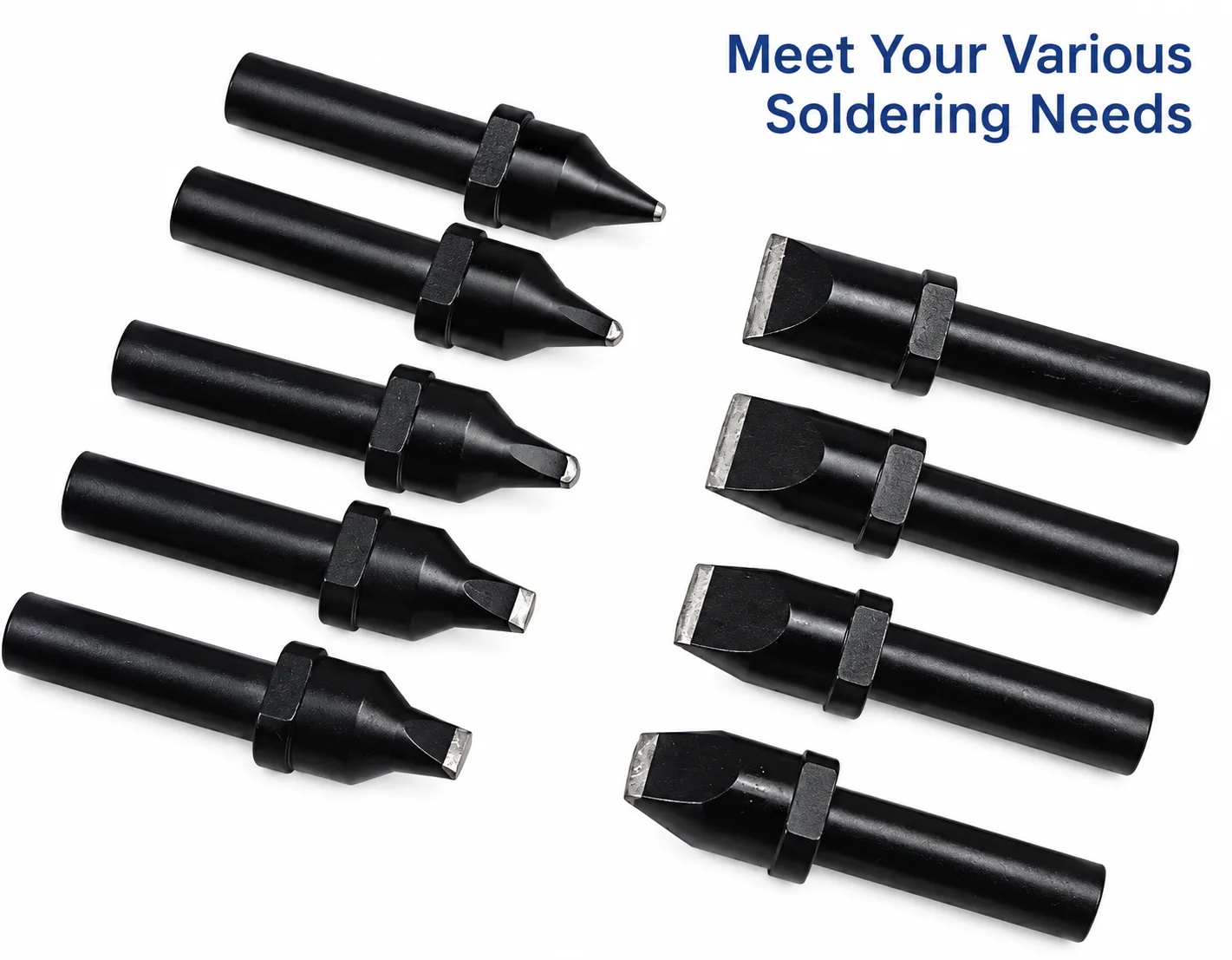
Different soldering iron tip shapes for different soldering applications.
What Does a Soldering Tip Do?
During a soldering cycle, the tip performs several practical functions:
- Transfers heat from the heater to the pad, lead, terminal or wire.
- Helps melt solder at the intended joint rather than merely heating the surrounding air.
- Makes precise contact with the solder joint, including joints that have limited clearance.
- Controls the soldering area through its working-face size and orientation.
- Supports consistency by giving the same programmed position a repeatable contact condition from cycle to cycle.
- Adapts the machine to the product: different PCB layouts, through-hole components, connectors and wire assemblies need different approaches.
The tip does not work alone. Temperature, dwell time, solder wire, flux, programmed motion and product fixturing are also part of the process. Still, a poorly matched tip can limit all of them because the machine cannot create a stable heat path where the tip does not make suitable contact.
Why Are There So Many Soldering Tip Shapes?
There is no universal soldering tip for every electronic assembly. A small PCB pad, a through-hole lead, a heavy terminal and a wire-to-connector joint do not need the same contact area or approach direction.
When selecting a tip, engineers commonly consider tip width, thickness, diameter, working-surface shape, tinned length and approach angle. These features determine how much heat can be delivered, how the tool can enter the available space, and whether the contact face sits naturally on the joint.
For example, a narrow tip can reach between closely spaced components, but it may not transfer enough heat to a larger terminal. A broader chisel-style face can transfer heat efficiently to a larger joint, but it may be unsuitable near plastic housings or adjacent components. The best choice is the one that fits the actual joint and process window, not simply the smallest or largest tip available.
Common Soldering Tip Types
The following examples show common families used for automatic soldering applications. Exact geometry and compatibility should always be checked against the machine model and the supplier's drawing.
PC Tip
PC tips are useful where a compact contact area and controlled access are needed. They can suit smaller pads, component leads and joints where PCB space is limited.
D Tip
D tips provide a broader, flatter working face than a fine point. That contact area can be helpful for joints that need more thermal contact, such as larger pads, leads, terminals or wire connections. The usable face must still match the joint so that it does not touch nearby features.
DV1 Tip
DV1 tips use an angled working-face arrangement. This can be useful when the soldering head needs to approach a joint from one side while keeping the body of the tip clear of nearby components. The selected angle and dimensions should follow the fixture and soldering direction, rather than being chosen by appearance alone.
DV2 Tip
DV2 tips are another angled style that can provide a different contact direction or working-face relationship. They are often considered where PCB access, terminal orientation or the motion path makes a straight approach less practical. A sample or clear product photos are especially helpful when comparing DV styles.
In the dimensional drawing below, A refers to width, B to thickness and C to tinned length where applicable. The drawing contains the full model range, so there is no need to reproduce every size as a separate table here.
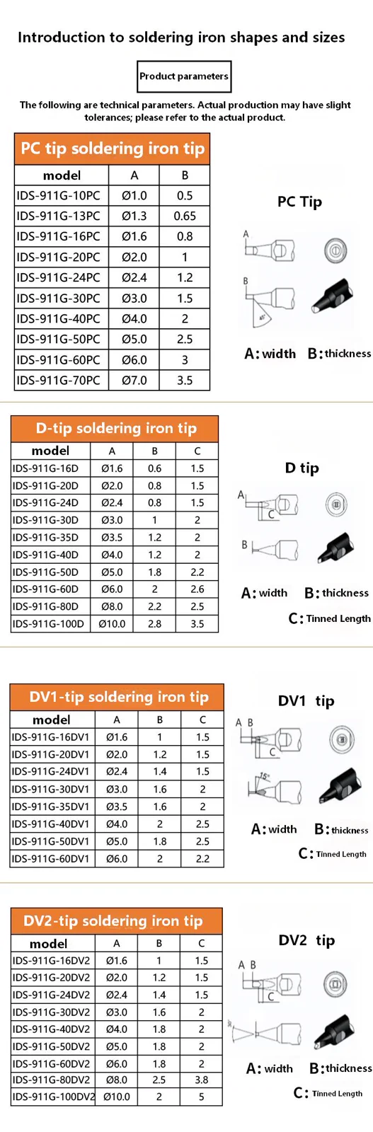
Examples of PC, D, DV1 and DV2 soldering iron tip dimensions and models.
How Is a Soldering Iron Tip Made?
Although the visible working end is small, a soldering iron tip is usually a layered component rather than an unprotected piece of copper. A typical construction starts with a copper-based core for efficient heat conduction. Protective layers can then be added to improve resistance to wear, oxidation and high-temperature use, while the working surface is prepared to accept solder.
The exact materials, layer sequence and thickness vary by tip design and manufacturer. In practical terms, the important balance is between thermal conductivity, wear resistance, oxidation resistance and tinning performance. Good heat transfer is valuable, but the working face also needs to remain stable under normal operating conditions. A tip that wets solder properly but wears too quickly, or one that lasts but transfers heat poorly, is not a useful production solution.
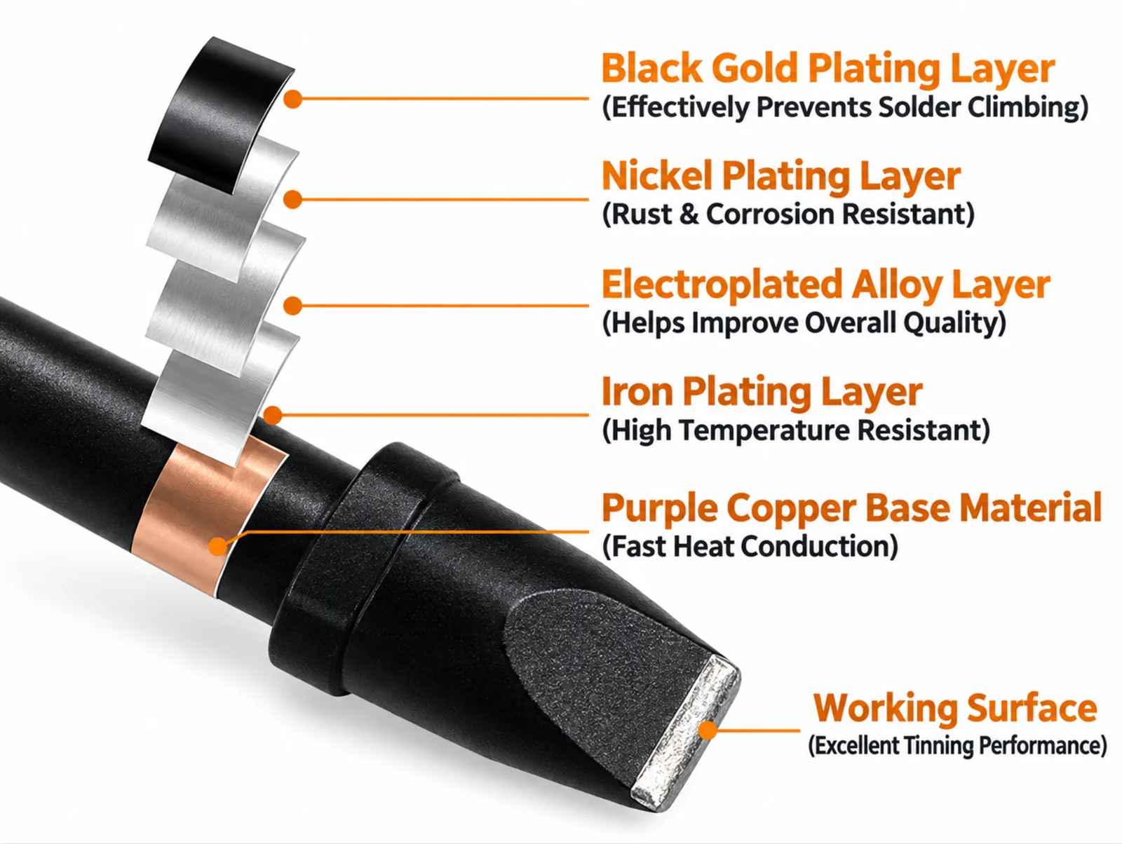
Typical multilayer structure of a soldering iron tip.
Why Tip Shape Matters in Automatic Soldering
In hand soldering, an operator may adjust their hand position instinctively. In an automatic soldering machine, the motion is programmed, so the tip needs to make the correct contact at a planned coordinate, height and angle every time.
If a tip is too small for the joint, heat transfer may be insufficient and the programmed soldering time may become longer. If it is too large, it may touch a nearby component, plastic connector body or adjacent pad. A suitable contact area lets heat move into the intended solder joint more efficiently while helping the process stay within the available PCB space.
This matters for PCB solder joints, connectors, terminals, wires, through-hole components and mixed electronic assemblies. It also matters for repeatability: once the correct geometry is found, the machine programme, fixture and tip can work as one controlled system.
Soldering Tips in Automatic Soldering Machines
Inside an automatic soldering machine, the tip normally works together with a heating system, solder wire feeding system, positioning mechanism and motion-control system. The machine brings the tip to the joint, applies heat for the programmed time, feeds solder as required, and moves to the next position.
The exact sequence varies with the product, but position, temperature, solder quantity and dwell time are all controlled together. The tip is therefore a small consumable with a large influence on the machine's final soldering performance. If its surface is oxidised, damaged or mismatched to the joint, it can affect wetting, cycle time and repeatability even when the rest of the system is operating normally.
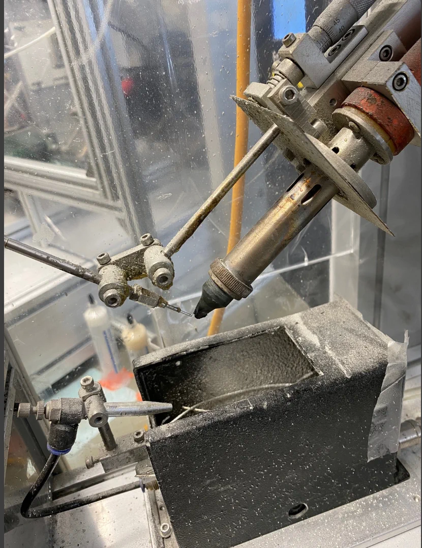
Soldering iron tip working inside an automatic soldering machine.
How to Choose the Right Soldering Iron Tip
Start from the actual application rather than from a tip catalogue. The following questions make the selection more reliable:
- What are the size and shape of the solder joint?
- How much PCB space is available around it?
- Is the part a pad, wire, terminal, connector or through-hole component?
- How much heat transfer is needed for the joint mass?
- From which direction can the soldering head approach?
- What temperature and cycle conditions will the process use?
- Which automatic soldering machine or soldering robot is involved?
- What tip lifetime is expected under the intended production conditions?
The best soldering tip is not necessarily the smallest or largest one. It should provide sufficient contact area and stable heat transfer for the actual soldering application.
How to Extend Soldering Tip Life
Tip life depends on process temperature, solder and flux chemistry, operating time and everyday handling. These habits usually help protect the working surface:
- Keep the working surface properly tinned when the equipment is in use.
- Avoid unnecessarily high soldering temperatures.
- Do not mechanically grind or file the plated surface.
- Remove oxidation with an appropriate tip-cleaning method.
- Use suitable solder and flux for the process.
- Avoid leaving the tip at high temperature for long periods without soldering.
- Replace tips that are damaged, heavily oxidised or no longer wet solder consistently.
Maintenance is not only about extending consumable life. It also helps keep the contact condition more consistent from one product batch to the next.
Custom Soldering Iron Tips from Southern Machinery
Southern Machinery can provide soldering iron tips with different shapes, dimensions and working surfaces for a range of automated soldering applications. In addition to standard PC, D, DV1 and DV2 styles, a custom soldering iron tip can be evaluated when a customer's joint geometry or machine arrangement needs something different.
For a useful evaluation, the following information is often enough to begin:
- Photos of the existing soldering tip
- Tip dimensions or a drawing
- Automatic soldering machine model
- PCB or product photos
- Solder-joint dimensions
- Component or terminal structure
- A short description, photo or video of the current soldering problem
This information helps confirm whether a standard design is suitable or whether a customised soldering tip, working face or machine-side setup should be considered.
Automatic Soldering Machines and Soldering Solutions
The tip is one part of a wider soldering solution. Southern Machinery also works with automatic soldering machines, soldering robots, customised soldering fixtures, solder feeding systems, soldering machine spare parts and soldering consumables.
For many applications, the answer is not simply to change the tip. It may involve the tip together with fixture positioning, solder-feed direction, programme settings or product access. Looking at those elements together is usually more useful than treating a soldering problem as an isolated consumable issue.
Conclusion
A soldering iron tip may be small, but it directly affects heat transfer, access, wetting and consistency in automatic soldering. Choosing the right shape, size and working surface helps an automatic soldering machine deliver a more stable process across PCB joints, terminals, wires and electronic assemblies.
If you are using an automatic soldering machine and cannot find the correct soldering tip, you can send Southern Machinery your tip dimensions, machine model, soldering product or application photos. We can help evaluate standard or custom soldering iron tips for different automated soldering applications.