In a wave soldering line, the PCB does not simply travel through the fluxer, preheat section and solder pot by itself. It needs a stable way to be carried, supported and positioned as the conveyor moves. Wave soldering titanium fingers—also called titanium conveyor fingers, PCB conveyor fingers or titanium PCB clamps—are the small mechanical parts that perform this job.
This guide explains designs, replacement checks and machine matching.
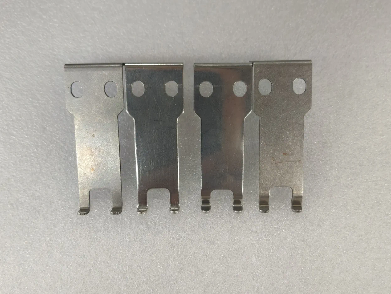
Examples of wave soldering titanium finger profiles.
What Are Wave Soldering Titanium Fingers?
A wave soldering titanium finger is installed on the conveyor chain or PCB transport mechanism of a wave soldering machine. It grips or supports the edge of a PCB while leaving the required side of the board available for process operations. Across the line, the fingers help keep the board in a repeatable position as it passes through fluxing, preheating and wave soldering.
In practical use, a suitable wave soldering finger needs to do several things at once:
- Hold the board securely enough to prevent unwanted movement during transport.
- Provide stable, repeatable contact at the board edge or specified clamping point.
- Leave the necessary soldering area exposed.
- Avoid collision with components, fixtures, guides or the conveyor structure.
- Remain suitable for the continuous heat and process environment of a production line.
Titanium alloy is commonly selected for this type of wave soldering spare part because it offers useful resistance to high-temperature and corrosive process conditions. Actual suitability and service life still depend on the finger design and operating conditions.
Why the Finger Shape Matters
There is no single “best” conveyor finger. The shape changes how the PCB is clamped, how much space is available around components, and how the finger connects to the chain. A profile that works well for one board family can be wrong for another one.
Key selection factors include:
- PCB thickness and allowable clamping width.
- Board edge location and the soldering area that must stay clear.
- Component height and clearance near the edge of the PCB.
- Conveyor chain style, mounting position and pitch.
- Finger width, height, thickness, hook shape and bending angle.
- The stability needed for the board size and production movement.
The result is a simple principle: select the shape from the machine and board, not from appearance alone.
Common Wave Soldering Titanium Finger Designs
L-Type Titanium Fingers
An L-type titanium finger uses a bent profile to create its mounting and clamping geometry. It is a familiar option where the conveyor mechanism and PCB path require an offset between the mounting area and the working end.
The supplied L-type example shows why a complete dimensional check is useful. It identifies an approximately 56 mm overall height, 18 mm and 23 mm upper dimensions, 1.5 mm material thickness and a 5 mm lower feature. Those values describe that reference part only; they should not be treated as a universal L-type standard.
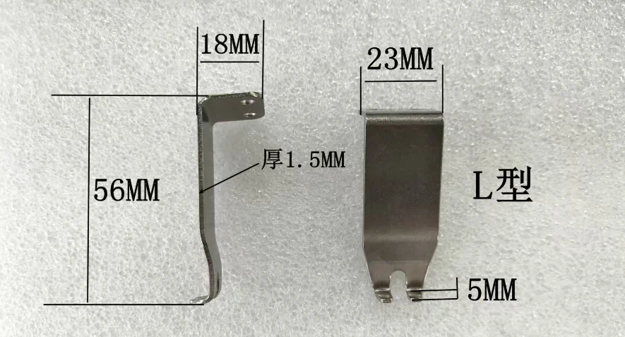
L-type titanium finger reference dimensions supplied for matching.
V-Type Titanium Fingers
V-type designs use a shaped clamping region that can suit board edges or conveyor arrangements where centred guidance and clearance are important. The exact V profile, opening, contact region and bend position affect whether the finger locates the PCB correctly and clears neighbouring hardware.
When replacing a V-type wave soldering finger, a front view alone is rarely enough. A side view, the original sample or a drawing helps confirm the depth, bend and chain-side configuration.
Flat-Top and Ultra-Thin Fingers
Flat-top fingers are useful where a flatter supporting or clamping relationship is required. Ultra-thin styles can be considered when the available clearance is tight and the finger must occupy as little space as possible. Neither description defines a complete part: the mounting, dimensions and board contact geometry still need to be checked.
J-Hook Fingers
J-hook titanium fingers use a hook-like lower feature for specific conveyor and board-support arrangements. Their geometry is especially dependent on the existing chain and mounting details. For this reason, a sample, a clear side photograph or the relevant drawing is normally the fastest way to avoid a mismatch.
Standard Replacements and Wave Soldering Spare Parts
For routine maintenance, a standard replacement may be enough when the existing finger shape and mounting are known. Typical needs include worn or damaged fingers, service stock and refurbishment of an older machine. The most useful starting point is one of the following:
- The wave soldering machine brand and model.
- Clear front, side and back photos of the existing wave soldering conveyor finger.
- A physical sample.
- A dimensional drawing or a list of critical measurements.
This information makes it possible to determine whether a standard titanium PCB clamp is appropriate or whether the replacement should be made to the existing geometry.
Custom Titanium Fingers: What Needs to Be Confirmed?
Custom titanium fingers are often the practical answer for legacy wave soldering machines, special board outlines, non-standard chain arrangements or applications with limited component clearance. Southern Machinery can evaluate custom titanium finger requests from an existing sample, a drawing, product photos or measured dimensions.
The key details are finger width and height, material thickness, upper mounting shape, holes or locating features, bends, lower clamping geometry, PCB contact area and clearance around the conveyor or components.
The image below illustrates two views of a customised profile. It gives a 20 mm upper dimension, 17 mm face width, 44 mm vertical section and 10 mm lower feature. It is a useful example of the way a part can be defined from measurable geometry, rather than evidence that every finger uses the same specification.
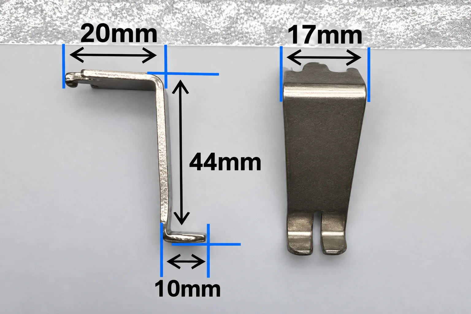
A customised titanium finger reference defined by key dimensions.
Drawing- and Sample-Based Matching
An engineering drawing can provide details that a photograph cannot: bend radius, tolerance, hole position, mounting interfaces and clearance. The original part is equally useful when the drawing is missing.
The technical drawing shown below is a customer/reference drawing for replacement matching. It includes legacy machine context such as VITRONICS, DOOVER and SOLTEC, and is shown only as an example of how a drawing can support a custom fit. It does not indicate a partnership, authorisation or OEM relationship with any of those brands.
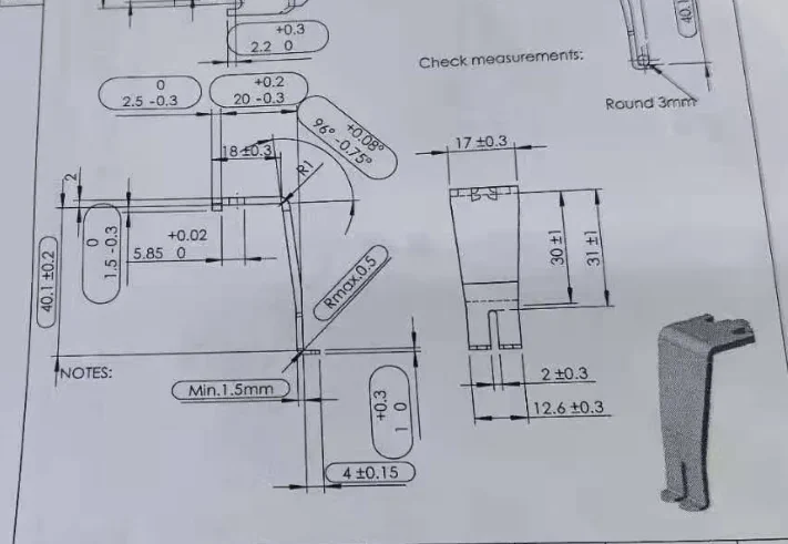
Reference drawing used as an example for drawing-based replacement matching.
A Simple Process for Ordering or Developing a Finger
Whether the request is for a standard spare part or a custom PCB conveyor finger, a clear process helps reduce fit issues:
- Identify the machine and application. Share the machine model, conveyor information and PCB use case.
- Confirm the existing geometry. Provide photos from multiple sides, a sample, a drawing or measured dimensions.
- Review the critical interfaces. Check board thickness, clamping width, chain mounting, hook shape and clearance.
- Make or confirm the sample. For custom work, verify the proposed configuration before volume production.
- Verify fit on the line. Confirm that the finger installs correctly, carries the board steadily and does not interfere with the process.
This sequence is particularly worthwhile where the equipment is old, the original part is no longer readily available, or the PCB has changed since the machine was installed.
Production Use and Typical Applications
Wave soldering titanium fingers are used in wave soldering machines, lead-free lines, PCB conveyor systems, THT assembly, EMS production, spare-parts replacement and customised board-transport fixtures. Batch packing helps protect the formed profiles during handling and supports practical spare-parts management.
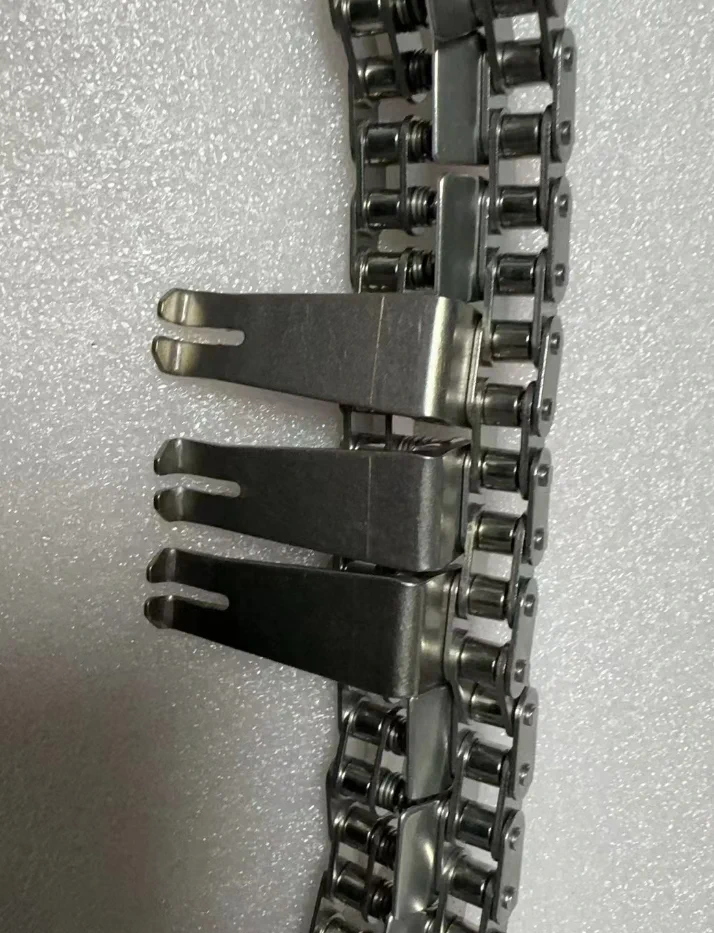
Titanium fingers installed on a PCB conveyor chain.
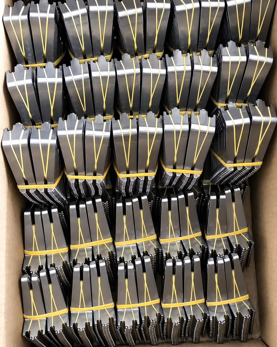
Batch-packed titanium fingers prepared for spare-parts supply.
Quality and RoHS Documentation
For applicable wave soldering titanium alloy finger products, Southern Machinery can provide RoHS compliance documentation on request. The supplied RoHS document identifies wave soldering titanium alloy fingers and several profile styles, including L-shape, V-shape, flat-top, ultra-thin and J-hook.
The supplied certificate is based on testing of a submitted sample. Documentation should therefore be confirmed against the requested configuration rather than treated as a blanket statement for every customised geometry or all products.
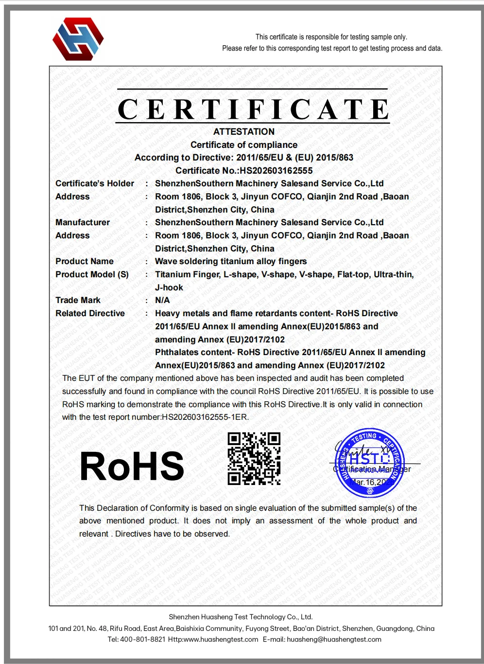
Supplied RoHS sample-test documentation for wave soldering titanium alloy fingers.
Checklist Before You Ask for a Quote
Sending the following details makes a wave soldering titanium finger enquiry faster and more accurate:
- Wave soldering machine brand and model.
- Photos of the current finger from the front, side and mounting side.
- A physical sample, drawing or measured dimensions.
- PCB thickness and required clamping width.
- Conveyor chain or mounting details.
- Component-clearance restrictions near the board edge.
- Required shape: L-type, V-type, flat-top, ultra-thin, J-hook or another profile.
- Required quantity and whether the request is for spares, refurbishment or a new line.
Conclusion
Wave soldering titanium fingers directly affect PCB transport, board stability and process clearance. Standard L-type, V-type, flat-top, ultra-thin and J-hook designs can cover many replacement needs, but custom geometry is often safer when the chain, board profile or machine layout is unusual.
For a reliable match, send Southern Machinery the machine information together with a drawing, sample, photos or key dimensions. That gives the engineering review a concrete basis for selecting or developing the right wave soldering conveyor finger before volume supply.