Reflow soldering is often described with a short list of oven temperatures and a conveyor speed. That is useful for loading a recipe, but it is not the profile that matters to a solder joint. The useful profile is the temperature-versus-time history of the fully populated PCB assembly as it moves through the oven.
That distinction matters when one board combines a large BGA, fine-pitch devices, small chip components, shields, connectors and a mix of copper areas. The same oven setpoints can produce very different board temperatures when the design, fixture, loading or product build changes.
This guide turns reflow profiling into a practical engineering workflow for EMS and PCBA teams. It focuses on how to measure the real assembly, set a defensible thermal window and keep the oven under control without treating a generic chart as a universal recipe.
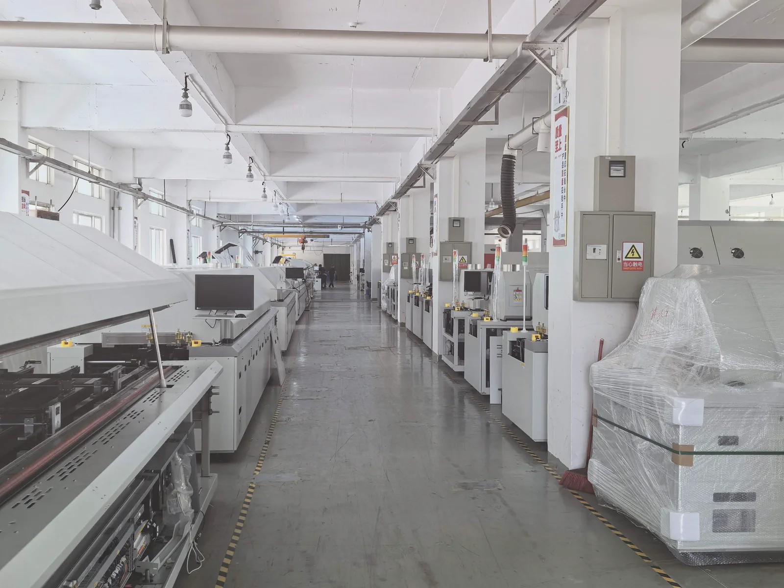
Production-line image supplied by Light for this article.
Start With the Product, Not the Oven Display
An oven recipe has two main inputs: zone temperatures and conveyor speed. Airflow, load condition, rail configuration and the particular machine also influence the result. The product profile is the output: what critical locations on the PCBA actually experience.
The process goal is therefore a balance. Every solder joint must receive enough thermal energy to wet and form a sound interconnection, while the hottest or most sensitive locations remain inside their allowable exposure limits. IPC-7530 describes this as a product-specific task, not a single setting that should be copied across every board.
For a new product, collect the limits before adjusting the oven:
- The solder-paste supplier's recommended reflow window for the exact alloy and flux system.
- Component-package peak-temperature and time limits from the relevant manufacturer data.
- Moisture-sensitivity handling requirements for exposed packages.
- Board constraints such as thickness, copper balance, panel format, warpage risk and fixtures.
- Product-specific concerns, including voiding, head-in-pillow, large thermal masses or sensitive connectors.
This creates a process envelope. Zone settings are then tuned to bring all measured locations into that envelope.
Build a Thermocouple Plan That Finds the Extremes
A profile is only as good as its measurement points. Placing every thermocouple (TC) on easy-to-reach pads can make a chart look clean while missing the real cold or hot location.
Use a fully populated, production-representative assembly whenever possible. Include the normal carrier, pallet, shield or hold-down arrangement if it travels through the oven in production. A board run bare during profiling can behave differently from the one that will actually be soldered.
At minimum, choose locations that are likely to heat at different rates:
- A high-thermal-mass or shadowed location, such as a large area-array package, shielded region or heavy copper area. It is often a candidate for the coldest solder joint.
- A low-mass, exposed location, such as a small chip area or bare board edge. It can become the hottest point.
- A temperature-sensitive component whose supplier limit could set the maximum allowable peak.
- Additional locations where the product makes them necessary: opposite sides of a large panel, dense connectors, the centre of a shielded assembly or package locations that are difficult to infer from the board surface.
An air-reference TC may be useful for diagnosing oven behaviour, but it is not a substitute for contact measurements on the assembly. KIC's technical guidance similarly recommends covering both hot and cold board locations and adding channels for sensitive components or area-array packages as needed.
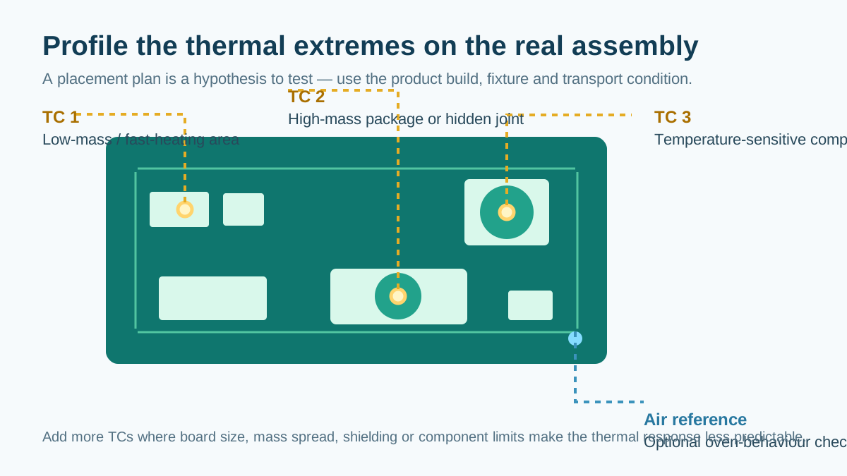
Original diagram by Light. It is a placement concept, not a substitute for product-specific TC selection.
Attach and Protect the TCs Properly
The bead must measure the intended feature rather than a nearby copper area, loose adhesive or the air around the board. Keep leads routed neatly and away from adjacent pads, and prevent exposed wire from touching conductive features. Confirm the attachment before every run.
The attachment method must survive the process and make stable thermal contact. High-temperature solder, conductive metal tape and qualified high-temperature adhesives are common options, but the correct method depends on the test board, package access and the profiler supplier's instructions. A loose or poorly coupled TC can create false readings and lead to a bad recipe decision.
For hidden joints, such as some BGA locations, the measurement approach needs particular care. The aim is to understand the temperature at the soldering-critical interface, not merely the temperature on a convenient package surface. Document the location, attachment method and channel number so a later profile can be compared meaningfully.
Read the Profile as a Window
Avoid qualifying a profile on peak temperature alone. The usual checks work together:
- Ramp rate: How quickly the assembly heats. Excessive ramp can raise thermal-stress risk and can make flux behaviour more difficult to control.
- Activation or equalisation stage: A soak may help thermal balance or support a specific paste system, but it is not automatically better for every design.
- Time above liquidus (TAL): The time spent above the alloy's liquidus temperature. It must be long enough for the intended wetting and joint formation, but should stay within the approved process window.
- Peak temperature: Verify the coldest critical joint reaches the required reflow condition while the hottest/sensitive location remains below its limit.
- Cooling rate: Cooling affects microstructure and mechanical stress. It should follow the approved material and assembly limits rather than a universal “as fast as possible” rule.
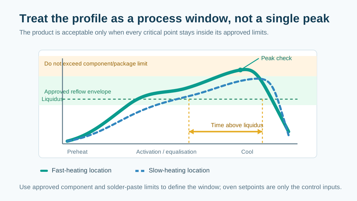
Original diagram by Light. The illustrated limits are conceptual; use approved supplier limits for production.
The safest review method is to look at all TC traces together. A green result on the hottest channel does not prove the coldest joint reflowed. Conversely, a cold BGA result does not justify raising the whole profile if a nearby connector or small component is already at its limit.
SAC305 Is a Starting Point, Not a Recipe
SAC305 is commonly written as 96.5Sn/3.0Ag/0.5Cu. Its liquidus is typically around 217–220°C, but a production profile cannot be selected from that value alone. Paste formulation, board mass, component finish, package limits and defect mechanisms all matter.
As an example, one Indium Corporation SAC305 paste data sheet gives a typical 1.0–2.5°C/s ramp, 45–60 seconds TAL and a 230–260°C peak range. The document also presents these figures as general product guidance rather than a performance guarantee. That is the right way to use a supplier chart: as a controlled starting window for the specific material, followed by measurement on the actual product.
Do not transfer a SAC305 recipe unchanged to SnPb, low-temperature SnBi, mixed-alloy or specialised low-voiding processes. Those systems have different melting behaviour and may have very different approved thermal windows. For assemblies with moisture-sensitive packages, follow the component maker's handling instructions and the applicable IPC/JEDEC moisture/reflow classification guidance.
Decide Whether a Linear or Soak Profile Fits the Product
Both ramp-to-spike (linear) and ramp-soak-spike approaches are used in production. The best choice is the one that meets the solder-paste and component limits while giving acceptable results for the board.
A linear profile may reduce total exposure time and can suit many modern no-clean paste systems. A controlled soak can help reduce thermal spread on assemblies with strong mass variation, and some paste systems use it to support flux activation or void-control strategies. Neither format should be selected by habit. Confirm it through the paste supplier's data, product profiling and defect evidence such as X-ray, cross-sectioning or reliability feedback where appropriate.
Separate Product Profiling From Oven Verification
There are two related but different controls:
- Product recipe validation proves that a particular PCBA, with its actual build condition, meets its thermal window.
- Oven performance verification checks whether the machine remains repeatable and behaves as expected over time.
This separation prevents a common mistake: treating a periodic oven check as proof that every product recipe is still valid. IPC-7801 addresses baseline and periodic oven-profile verification, calibration and maintenance; it explicitly distinguishes that work from developing an assembly product profile.
In practical production control, keep a released profile record for each board family or qualified recipe. Record the board revision, paste, alloy, conveyor speed, zone setpoints, TC map, fixture condition, profile results, date and approver. Re-profile after meaningful changes: a new board revision, component/package change, different paste, new pallet, oven maintenance affecting the thermal system or a quality trend that points to soldering.
Control Atmosphere, Equipment Condition and Board Support
Nitrogen can improve wetting on challenging surfaces for some materials, but it is not a universal requirement. The oxygen level, timing and economic justification should be set from the paste supplier's guidance and the validated process. Do not adopt a fixed residual-oxygen number from an unrelated product.
The oven itself also needs routine care: calibrated temperature measurement, clean process chamber and extraction path, stable conveyor transport and repeatable airflow. For wide or thin panels, evaluate whether centre support, a carrier or another transport arrangement is needed to keep the board flat through the thermal cycle. Support can reduce the mechanical contribution to warpage, but it must be validated because it also changes heat flow into the assembly.
A Short Release Checklist
Before releasing or changing a reflow recipe, confirm the following:
- The exact paste/alloy and component limits have been reviewed.
- TCs cover the expected hot, cold and sensitive locations on a representative build.
- Attachments and wire routing were checked before the run.
- Every trace meets the approved ramp, TAL, peak and cooling limits.
- The board, fixture and production transport condition match the profiled condition.
- Results, recipe inputs and approval are recorded for repeatability.
- A change-control trigger exists for paste, board, package, fixture or oven changes.
Conclusion
A reliable reflow profile is a measured product-level process, not a temperature table copied from another line. Start with material and package limits, instrument the thermal extremes of the real assembly, evaluate the complete time-temperature window and keep product qualification separate from oven health checks. That approach gives process engineers a clearer basis for reducing soldering defects while protecting components, boards and production repeatability.
References
- Original reference article: PCBA Manufacturing Process Specification — SMT Reflow Profile
- IPC-7530B status: Guidelines for Temperature Profiling for Mass Soldering Processes (Reflow & Wave)
- IPC-7801: Reflow Oven Process Control Standard
- IPC/JEDEC J-STD-020E: Moisture/Reflow Sensitivity Classification
- Indium Corporation SAC305 PicoShot WS-5M Product Data Sheet
- KIC Thermal: Process Guidelines to Ensure Optimal SMT Electronics Assembly