Timing belts are widely used in servo-driven machinery because they transfer motion between a motor and a driven mechanism with a defined tooth-to-pulley relationship. In day-to-day maintenance, however, replacement is rarely as simple as reading a part number. Printing can wear away, a belt may be removed before it is documented, and several visually similar belts may be stocked around the same line.
When the marking is missing, the practical way forward is to identify the tooth profile, pitch, number of teeth, belt width, and pitch length. Those details describe the engagement with the pulley much more reliably than an overall length measurement alone. This guide explains how these parameters work, where servo motor timing belts appear in automation and electronics-manufacturing equipment, and how to collect useful information for a replacement check.
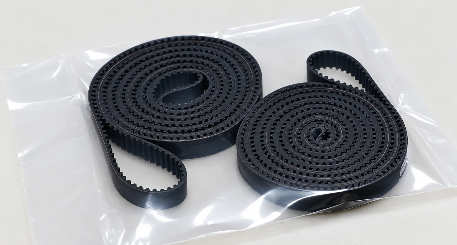
What Is a Timing Belt?
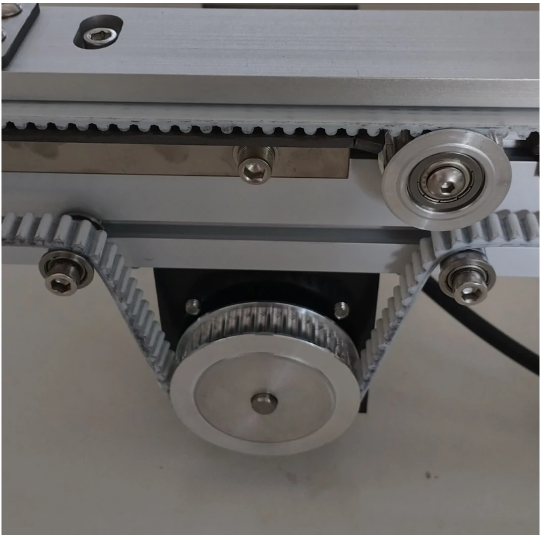
Timing belt, synchronous belt, and toothed belt are closely related terms. In industrial use, they normally refer to a flexible belt with regularly spaced teeth on its inside surface. Those teeth mesh with a matching timing belt pulley.
An ordinary friction belt transfers motion mainly through contact friction on a pulley surface. A synchronous belt transmits through the engagement of belt teeth and pulley grooves. Under correct tension, alignment and load conditions, that engagement maintains a defined transmission relationship rather than relying on friction to hold the ratio. It is still not a promise of “zero slip”: poor tension, wear, contamination, misalignment or overload can lead to tooth wear or tooth jumping.
Why Are Timing Belts Used with Servo Motors?
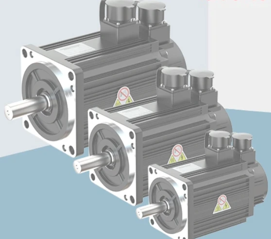
Servo motors are commonly selected where controlled speed, position and repeated motion are required. A servo motor belt drive lets the motor be positioned away from the driven shaft, while the timing belt carries rotary motion to another pulley, shaft or linear mechanism.
Synchronized Transmission
Matching teeth and pulley grooves help preserve the intended transmission relationship in normal operation. That is valuable where motion at the driven side needs to remain coordinated with the servo motor’s rotation.
Low Noise and Flexible Layout
Compared with many gear-based arrangements, a correctly configured timing-belt drive can operate relatively quietly. It also gives machine builders freedom to offset the motor from the driven shaft instead of placing both on the same centreline.
No Oil Lubrication and Repetitive Motion
Timing belt systems normally do not require oil lubrication. Their simple routing also suits repeated transport and positioning tasks, provided that the chosen belt, pulley, tensioning and guarding match the actual machine design.
Where Are Servo Motor Timing Belts Used?
Timing belts appear across industrial automation, but their use depends on the mechanism—not every machine uses the same transmission method. Typical examples include linear modules, XY motion systems, packaging machinery, automated assembly stations, inspection equipment, robotics and material-handling systems.
In electronics manufacturing equipment, they may be found in PCB loaders and unloaders, PCB conveyors, pick-and-place mechanisms, inspection machines, transport sections and component-insertion equipment. A belt drive is particularly useful where a motor must be mounted away from the moving or driven element.
Timing Belt Tooth Profiles Explained
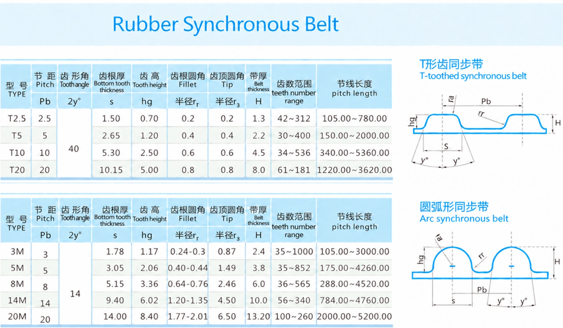
The pitch is essential, but it does not tell the whole story. The tooth geometry must also match the pulley. The supplied reference chart illustrates two broad families often encountered in industrial equipment.
Trapezoidal Timing Belts
The T-series uses a trapezoidal tooth profile. Common examples are T2.5, T5, T10 and T20; the number normally indicates pitch in millimetres. For example, a T5 timing belt has a 5 mm pitch and trapezoidal teeth.
Curvilinear or Arc-Tooth Timing Belts
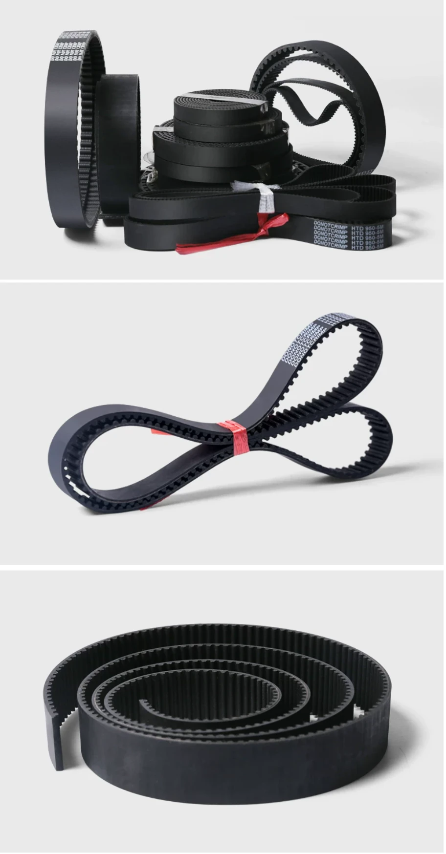
Curvilinear, rounded or arc-tooth belts are commonly designated 3M, 5M, 8M, 14M and 20M. Here too, the number generally corresponds to pitch in millimetres. A 5M belt therefore has a 5 mm pitch, but a different tooth form from a T5 belt. Terms such as HTD may also appear in existing belt markings; the actual pulley and tooth geometry still need to be confirmed.
A T5 belt and a 5M belt both have a 5 mm pitch, but their tooth profiles are different. They should not be treated as interchangeable without checking the pulley profile.
Understanding Timing Belt Pitch
Pitch is the distance between corresponding points on adjacent teeth—normally described as the centre-to-centre spacing from one tooth to the next. It establishes the tooth spacing that the belt must share with its pulley.
The most useful relationship for an endless synchronous belt is:
For example, if the pitch is 5 mm and the belt has 436 teeth, the calculation is 5 mm × 436 = 2180 mm pitch length. This is especially useful when belt printing is absent but the tooth count and pitch can be measured.
Pitch: 5 mm
Number of teeth: 436
5 mm × 436 teeth = 2180 mm pitch length
How to Identify an Unknown Timing Belt
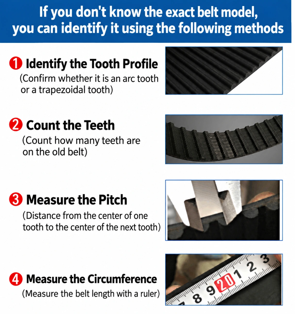
The image below is a useful field reminder, but the identification should be documented in words and measurements as well. A phone photo of the belt’s side profile and a photo of the mating pulley can save a repeat visit.
1. Check the Belt Marking
Inspect the outer surface first. A partly readable marking may include a profile, pitch length, tooth count or manufacturer-specific code, such as T5, 5M or another family designation. Marking conventions vary, so treat the printing as evidence to verify rather than as a complete specification on its own.
2. Identify the Tooth Profile
Decide whether the teeth are trapezoidal or curvilinear/arc-shaped. A close, well-lit side photo is more useful than a distant photograph of the whole belt. When the shape remains uncertain, inspect the pulley too—the belt and pulley are a matched set.
3. Measure the Pitch
Measure between matching points on adjacent teeth. To reduce reading error, measure across several pitch intervals, then divide by the number of intervals actually spanned. For example, a centre-to-centre measurement from the first of ten adjacent teeth to the tenth spans nine intervals, not ten.
4. Count the Teeth and Measure Width
Count every tooth around the full belt. Then use a caliper to measure width rather than relying on a rough ruler reading. A 10 mm, 15 mm and 20 mm belt can share the same profile and pitch length while still being different replacement specifications.
5. Confirm Pitch Length
Cross-check the length with pitch × tooth count. Do not substitute an arbitrary outside-circumference measurement for pitch length: the outside surface changes with belt thickness and does not identify the tooth geometry.
Timing Belt Technical Reference
The following values are general dimensional references based on the supplied belt specification chart. Always confirm the required pulley and belt profile before replacement.
Trapezoidal Timing Belts
| Type | Pitch (mm) | Tooth Angle | Bottom Tooth Thickness (mm) | Tooth Height (mm) | Root Fillet Radius (mm) | Tip Radius (mm) | Belt Thickness (mm) | Teeth Range | Pitch Length Range (mm) |
|---|---|---|---|---|---|---|---|---|---|
| T2.5 | 2.5 | 40° | 1.50 | 0.70 | 0.2 | 0.2 | 1.3 | 42–312 | 105.00–780.00 |
| T5 | 5 | 40° | 2.65 | 1.20 | 0.4 | 0.4 | 2.2 | 30–400 | 150.00–2000.00 |
| T10 | 10 | 40° | 5.30 | 2.50 | 0.6 | 0.6 | 4.5 | 34–536 | 340.00–5360.00 |
| T20 | 20 | 40° | 10.15 | 5.00 | 0.8 | 0.8 | 8.0 | 61–181 | 1220.00–3620.00 |
Curvilinear / Arc-Tooth Timing Belts
| Type | Pitch (mm) | Tooth Angle | Bottom Tooth Thickness (mm) | Tooth Height (mm) | Root Fillet Radius (mm) | Tip Radius (mm) | Belt Thickness (mm) | Teeth Range | Pitch Length Range (mm) |
|---|---|---|---|---|---|---|---|---|---|
| 3M | 3 | 14° | 1.78 | 1.17 | 0.24–0.3 | 0.87 | 2.4 | 35–1000 | 105.00–3000.00 |
| 5M | 5 | 14° | 3.05 | 2.06 | 0.40–0.44 | 1.49 | 3.8 | 35–852 | 175.00–4260.00 |
| 8M | 8 | 14° | 5.15 | 3.36 | 0.64–0.76 | 2.46 | 6.0 | 36–565 | 288.00–4520.00 |
| 14M | 14 | 14° | 9.40 | 6.02 | 1.20–1.35 | 4.50 | 10.0 | 56–340 | 784.00–4760.00 |
| 20M | 20 | 14° | 14.00 | 8.40 | 1.77–2.01 | 6.50 | 13.20 | 100–260 | 2000.00–5200.00 |
Why Belt Width Matters
Two belts can have the same 5 mm pitch, 436 teeth and 2180 mm pitch length while still not be the same item. A 10 mm-wide belt, a 15 mm-wide belt and a 20 mm-wide belt each require a compatible pulley width and machine layout. Width is therefore part of the replacement specification, not a minor packing detail.
Never identify a timing belt using length alone. Confirm tooth profile, pitch, tooth count, pitch length and width with the existing pulley whenever possible.
Timing Belt Manufacturing and Dimensional Control
For industrial timing belts, dimensional consistency supports correct engagement with the pulley and stable tracking in the designed drive arrangement. The supplied manufacturing information states a thickness tolerance of ±0.1 mm and a width tolerance of ±0.2 mm.
Those figures describe belt dimensions. They are not a machine-positioning tolerance, a guaranteed axis accuracy or a claim about overall system performance. The result at the machine level also depends on the pulley, tension, mechanical structure, servo tuning and operating condition.

Common Mistakes When Replacing a Timing Belt
Selecting by Length Only
Belts of a similar length may have different pitches and tooth profiles. Length by itself cannot prove compatibility.
Assuming T5 and 5M Are the Same
Both labels can indicate 5 mm pitch, but their tooth geometries differ. Reusing the existing pulley without checking profile can cause poor engagement.
Ignoring Width or Measuring Only the Outside
Width affects pulley compatibility and available clearance. Measuring only an outside circumference can also be misleading because the replacement reference is normally pitch length, not an arbitrary outer path.
Ignoring the Pulley or Guessing from Appearance
The pulley provides valuable evidence about tooth form. Belts from different families can look similar in ordinary photos, so take a close tooth-profile image rather than making a selection by general appearance.
What Information Should You Send for a Replacement Timing Belt?
If a printed model is readable, photograph it before removing the belt. If it is not, collect the following information:
- Belt model or visible marking
- Tooth profile and close-up tooth photo
- Pitch
- Total number of teeth
- Belt width, preferably measured with a caliper
- Calculated pitch length
- Overall belt photo and pulley photo
- Machine model and the servo-driven application
- Required quantity
These measurements and photos can normally support a preliminary identification. The final selection should still be checked against the mating pulley and the machine’s original requirements.
Example: Identifying a Servo Motor Timing Belt
Practical Example
An automation machine has a timing belt between a servo motor and the driven mechanism. The measured pitch is 5 mm, the belt has 436 teeth, and the width is approximately 15 mm.
5 mm × 436 teeth = 2180 mm pitch length
At this point, the pitch, tooth count, pitch length and approximate width are known. One decisive parameter remains: tooth profile. A close side photo must establish whether the belt is T5 trapezoidal or 5M curvilinear before the replacement is selected.
FAQ About Servo Motor Timing Belts
Can a timing belt be used with a servo motor?
Yes. Timing belts are commonly used in servo-driven industrial machinery to transfer synchronized rotary motion from a motor to another shaft or mechanism.
Is a synchronous belt the same as a timing belt?
In most industrial contexts, both terms describe a toothed belt designed to engage with a matching toothed pulley.
How do I know my timing belt pitch?
Measure the spacing between corresponding points on adjacent teeth, or measure across a known number of tooth intervals and divide by that interval count. A visible marking may provide a useful cross-check.
What do T5 and 5M mean?
T5 generally denotes a trapezoidal timing belt with 5 mm pitch. 5M generally denotes a curvilinear or arc-tooth synchronous belt with 5 mm pitch. The shared pitch does not make the tooth forms interchangeable.
How do I calculate timing-belt length?
For an endless synchronous belt, use Pitch Length = Pitch × Number of Teeth. For example, 5 mm × 436 teeth = 2180 mm pitch length.
What if the belt model cannot be read?
Measure the pitch and width, count the teeth, calculate pitch length, and provide clear photos of the tooth profile and pulley. This creates a better basis for a preliminary identification.
Final Thoughts
Timing belts may look simple, but a useful replacement specification contains more than an overall length. The most valuable checks are the tooth profile, pitch, tooth count, pitch length, width and the mating pulley. For servo motor and industrial automation systems, confirming those details before purchase helps avoid an avoidable mismatch.
If you are reviewing a belt used on SMT, THT or another automation machine, see the existing servo motor timing-belt component page for a concise component overview.
Need Help Identifying an Industrial Timing Belt?
Southern Machinery supports SMT, THT and industrial automation equipment, including replacement components for servo-driven and motion-control systems. Send belt photos, tooth-profile information, pitch, tooth count, length, width and machine model; we can review the available information and check the corresponding specification.
Send Belt InformationRequest a Quote
References
- Belt photographs and technical-reference chart: supplied by Light for this article.
- Replacement verification: confirm the required belt and pulley profile against the original machine documentation and the mating pulley before ordering.