
Load & Clamp
PCB enters, width adjusts and the board is located and clamped.
Learn more
The manual states a 3-second PCB installation time.
THT Automation · Odd-Form Insertion
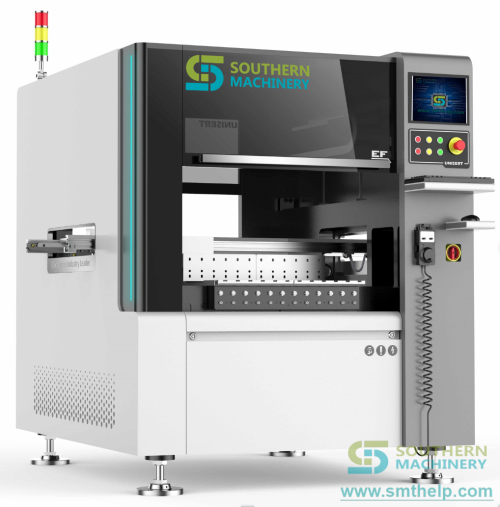
S7020T Automatic Terminal Insertion Machine. Automated feeding, vision correction, insertion and clinching for tact switches, connectors, copper inserts and axial terminals.
Component applications
For through-hole parts that are bulky, irregular, force-sensitive or need a controlled clinch, the insertion path is engineered around the actual component and packaging.
The drawings below are classification icons, not component photographs. Feeder and tooling suitability are confirmed with your samples.
Working process
A controlled flow from board registration to a completed, logged insertion cycle. Expand a step for the published process detail.
PCB enters, width adjusts and the board is located and clamped.
The manual states a 3-second PCB installation time.
Camera reads actual holes and corrects the offset against NC data.
Published automatic correction accuracy: 0.015 mm.
Bowl, track or tape feeder presents the component to the head.
Feeder selection follows component packaging.
The head places the part while the selected force-monitoring option checks the cycle.
Insertion force detection is shown as optional in the published specification.
Tooling forms the selected clinch and verifies insertion completion.
Inward, outward and N-form clinching are listed for the family.
Production data is recorded; manual or inline handling moves the board on.
Automatic load/unload is configuration-dependent.
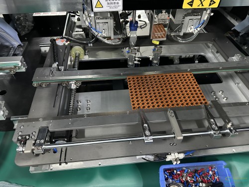
Southern Machinery S7000 / S7020T machine-family insertion area.
Machine capability
Open a capability to see how it is used in the insertion cycle. Published facts are separated from configuration advice.
Feed system
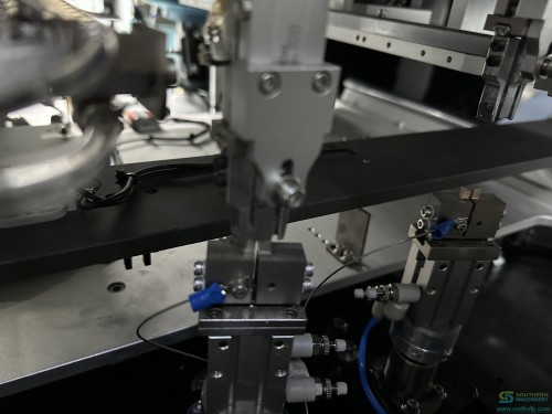
Packaging is not a secondary detail: it determines the feeder, layout and changeover plan. Southern Machinery matches the feed solution to the component you actually receive.
Need to choose the feeder before you quote?Send a terminal sample and its actual packaging; we will review the feed path with you.
Request Feed EvaluationTechnical specifications
Select a category rather than searching one long table. Values below are taken from the S7020T published manual or the related S-7000T solution document.
Theoretical values need to be read with the part type and head configuration.
| Insert part object | Tact switch · strip connector · copper insert (iron) · axial braided |
|---|---|
| Theoretical speed | 0.6 s/point tact switch · 0.55 s/point connector · 0.55 s/point copper insert · 1 s/point axial braided |
| Worktable resolution | 0.001 mm/pulse |
| Point-to-point positioning | 0.025 mm |
| Repeat positioning | 0.05 mm |
Board dimensions and handling options for the published platform.
| Minimum PCB | 80 × 80 mm |
|---|---|
| Maximum PCB | 380 × 280 mm |
| PCB installation | 3 seconds |
| Width handling | Automatic width adjustment listed as a special function |
| Load / unload | Manual or automatic PCB load and unload, configuration dependent |
Family capability data from the S-7000T terminal insertion solution sheet.
| Terminal thickness | 0.5–1.2 mm |
|---|---|
| Insertion angle | 360°, in 1° increments |
| Clinch modes | Inward clinching · outward clinching · N form |
| Insertion rate | Up to 2 insertions/second at 5.08 mm pitch |
| Insertion heads | 1 to 4, optional |
Component packaging drives feeder selection.
| Bulk parts | Tact switch, connector and copper insert |
|---|---|
| Axial braided | 52 mm tape |
| Bulk feed system | Bowl feeder + track |
| Axial feed system | Tape feeder |
| Material confirmation | Material QR code scanning listed as a special function |
Vision functions are used for correction, visual programming and production checking.
| Automatic correction | 0.015 mm |
|---|---|
| Programming | Online visual programming · visual correction · Excel format |
| Positioning | 0.025 mm point-to-point · 0.05 mm repeat positioning |
| Force detection | Optional insertion force detection |
Published HMI, programming and interface data.
| Control system | Windows-based intelligent insertion control system |
|---|---|
| Display | 17-inch colour LCD |
| Data input | USB · manual entry |
| Interface | RS-232C |
| Servo motion | Panasonic controller and motor drive stated in source material |
Plan final services against the quotation drawing and local code.
| Power | AC220V ±10V, single phase, 50/60 Hz |
|---|---|
| Manual power entry | 1.6 kVA · 2.0 kW maximum |
| Air | 5–6 kgf/cm² · 0.6 m³/min compressed air consumption |
| Noise | 70 dB |
| Manual environment | 5–25 °C; 20–95% RH (solution sheet also states 30–70% RH) |
These values vary across first-party documents. Use the technical data note and obtain the final configuration drawing.
| Manual dimension | 2160 × 1330 × 1530 mm |
|---|---|
| Manual weight | 1500 kg |
| S-7000T sheet dimension | 1700 × 1300 × 1600 mm (2-head configuration) |
| S-7000T sheet weight | 1200 kg |
Terminal & clinching capability
Clinch form, hole geometry and head count are tooling decisions that should be validated on a production-representative sample board.
Illustrative joint-direction schematic. Final clinch tooling is based on the component and required joint.
Validate the clinch with a real board.Send the component and PCB sample so the joint form, tooling and required pull-test plan can be reviewed.
Send Sample DetailsMachine gallery
Machine-family photos focused on the insertion area, feeding and clinching details. Select a thumbnail or open any image for a full-screen view.
Gallery images illustrate the S7000 / S7020T terminal insertion machine family and its production mechanisms.
Production video
Video players are not requested until a visitor chooses a clip. No videos autoplay and YouTube is used in privacy-enhanced mode after click.
Configuration builder
This is a front-end planning aid, not an automatic quotation. The final configuration is confirmed only after component and PCB evaluation.
Select a starting point. The summary gives an equipment engineer a clearer evaluation brief.
Payback calculator
A conservative, front-end estimate based primarily on labour savings. It does not claim yield, rework, floor-space or quality savings.
Installation planning
The final drawing takes priority. These published requirements are a practical planning starting point for your facilities and commissioning team.
AC220V ±10V, single phase, 50/60 Hz. Source documents state 1.6 kVA / 2.0 kW max and 2 kVA; plan the circuit to the final electrical drawing.
Published requirement is 5–6 kgf/cm² and around 0.6 m³/min. Regulate air at the machine rather than assuming line pressure is stable.
Manual states 5–25 °C and 20–95% RH; solution sheet states 30–70% RH. Use the tighter condition in your local site plan.
Confirm power, air gauge and a clear working area. Follow the current operating manual and your site safety procedure.
The manual identifies the computer as dedicated to the machine. Keep control software and media under your qualified maintenance process.
Manual loading or automatic load/unload affects conveyor interfaces, board flow and floor layout. Review them with the final configuration.
Technical evaluation
Send us the component, PCB drawing or sample. We will review the application as an insertion process, not just match it against a catalogue line.